闲来写点FPGA代码——4位无符号二进制乘法器
johncheapon 于 2014年09月23日 发表在 电路设计与调试
个人觉得自己写一些基本的VHDL代码可以把基本功给打扎实,一个复杂的系统往往是由无数很简单的单元组成的。
用FPGA做运算确实不如CPU方便,但运用得当的话,还是有不少优越性的。
硬件实现乘法运算有好几种:
1、最原始的就是移位相加,最经济,但速度慢。
2、组合逻辑乘法器,也叫并行乘法器,直接将每一种结果枚举然后通过查表 算结果,这种方式理论上最快,但很占资源,并且由于大量使用组合逻辑,在实际的FPGA实现时,会导致逻辑延迟较大,速度很难做得很快。
3、折中方案,例 如流水线、加法树乘法器。在组合逻辑中间插入时序单元,因为FPGA内部触发器资源相对较为丰富,而组合逻辑资源,也就是查找表资源则比较宝贵,所以需要 充分利用FPGA内部的时序单元,这样虽然会多了几个周期,但是最高支持的时钟频率Fmax(这个Fmax是搞FPGA设计时所需要用到的一个很重要的参 数)会提高,整体速度自然也会得到弥补。
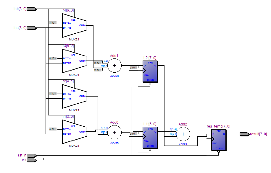
本文介绍的就是笔者自己编写的一种用加法器和时序逻辑单元来实现的一种4x4二进制无符号乘法器。
(--后面的内容是VHDL注释)
贴代码:
--The reference of library
library ieee;
use ieee.std_logic_1164.all;
use ieee.std_logic_arith.all;
use ieee.std_logic_unsigned.all;
--statement of entiy
entity MUL4X4 is
port--I/O port
(
clk:in std_logic;--clock&reset
rst_n:in std_logic;
ina:in std_logic_vector(3 downto 0);--input 4 bits data
inb:in std_logic_vector(3 downto 0);
result:out std_logic_vector(7 downto 0)--output 8 bits data
);
end MUL4X4;
--VHDL architecture
architecture RTL1 of MUL4X4 is
signal r1:std_logic_vector(3 downto 0);
signal r2:std_logic_vector(4 downto 0);
signal r3:std_logic_vector(5 downto 0);
signal r4:std_logic_vector(6 downto 0);
signal L1:std_logic_vector(5 downto 0);
signal L2:std_logic_vector(7 downto 0);
begin
process(inb,ina)--combination logic to create the r1~r4 from input data
begin
if inb(0)='1'then
r1<=ina;
else
r1<="0000";
end if;
if inb(1)='1'then
r2<=ina&'0';
else
r2<="00000";
end if;
if inb(2)='1'then
r3<=ina&"00";
else
r3<="000000";
end if;
if inb(3)='1'then
r4<=ina&"000";
else
r4<="0000000";
end if;
end process;
process(clk,rst_n)--the first piple,also the first add
variable r1t:std_logic_vector(3 downto 0);
variable r2t:std_logic_vector(4 downto 0);
variable r3t:std_logic_vector(5 downto 0);
variable r4t:std_logic_vector(6 downto 0);
variable L1t:std_logic_vector(5 downto 0);
variable L2t:std_logic_vector(7 downto 0);
begin
if rst_n='0'then
r1t:="0000";
r2t:="00000";
r3t:="000000";
r4t:="0000000";
L1t:="000000";
L2t:="00000000";
elsif clk'event and clk='1'then
r1t:=r1;
r2t:=r2;
r3t:=r3;
r4t:=r4;
L1t:=(r1t&'0'&'0')+(r2t&'0');
L2t:=(r3t&'0'&'0')+(r4t&'0');
end if;
L1<=L1t;
L2<=L2t;
end process;
process(clk,rst_n)--the second add
variable L1tt:std_logic_vector(5 downto 0);
variable L2tt:std_logic_vector(7 downto 0);
variable res_temp:std_logic_vector(7 downto 0);
begin
if rst_n='0'then
L1tt:="000000";
L2tt:="00000000";
res_temp:="00000000";
elsif clk'event and clk='1'then
L1tt:=L1;
L2tt:=L2;
res_temp:=(L1tt&'0'&'0')+L2tt;
end if;
result<=res_temp;--output the result
end process;
end RTL1;
综合以后的RTL视图: